Computer Controlled Machining
This week we had to do something big, all the weeks we spent on computer learning to design in 2d and 3d was to come handy now. Week 3 of Computer controlled machine had set a platform for this week's assignment. At vigyan Ashram we do not have a CNC machine, thus we had to go to College of Engineering Pune to use the shopbot machine there. Thus I got only one day to spend with the machine Thus we do not have much time to for trails, we have to get the things right in the first attempt.
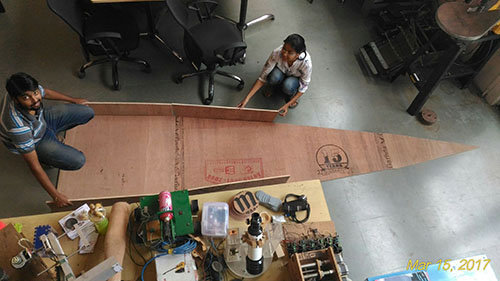
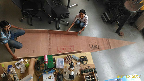
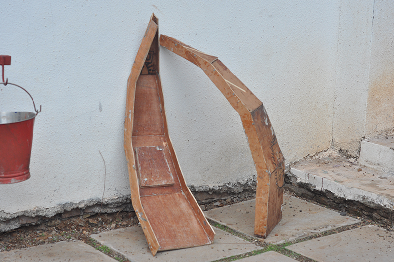
My final project is making a portable dome out of Natural Composites this would require a mould to cast the matrics and the fibres, thus I decided to make a mould out of plywood.It would be 900mm*3300mm made in 12 mm plywood sheets.
I would probably need one more mould for the casting process as the it will be used 16 times but I want to try doing it once and correct any mistakes done here in the other mould.
Deigning the mould
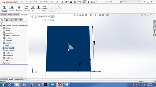
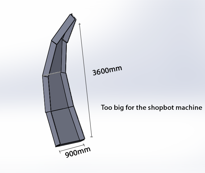
I started by designing parts in solidworks, I had to design a mould which would look something like this
 Final deisgn after renderng in solidworks
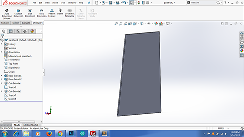
I realised that the whole mould can not be designed in a single sheet, the size of the mould is 900mm*3600mm which the huge for the shopbot machine we had.
Plus the mould is curving in 3D, the shopbot machine we have is 2.5 axis machine and it is incapable of handling such curves I was wrong when I said this, Neil during my review correccted me, he told me that a log of wood can be milled on one side and then flipped over to mill on the other side, this way I can make the curves that I want.

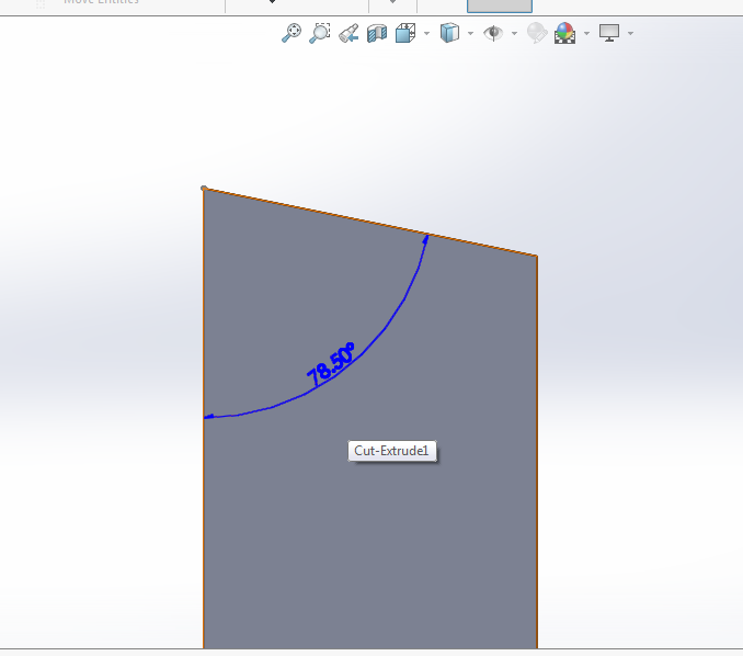
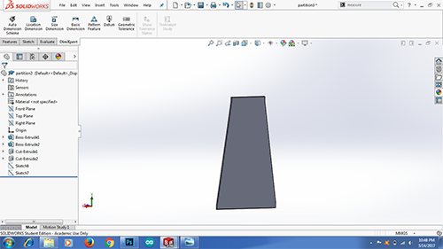
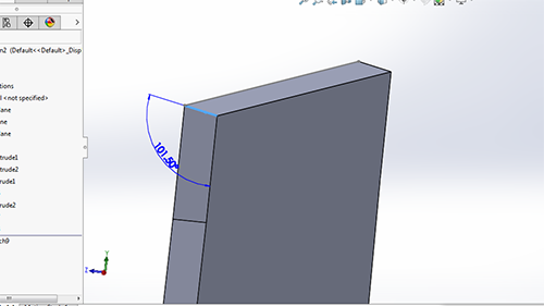 Curving mould in 3D
Thus I divide the design in 4 different parts in and saved four different files in solidworks.
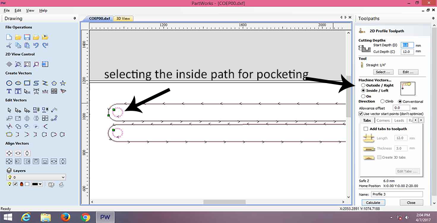
Unfortunately my design does not have pocketting, it is all profilling which is explaind further down.
I checked wether they assemble in solidworks, and they did withouth interference. I gave it a nice wood apperance.

Download the original files part1
Download the original files part2
Download the original files part3
Download the original files part4
Download the original files Assembly
Download the original .stlfiles part1
Download the original .stlfiles part2
Download the original .stlfiles part3
Download the original .stlfiles part4
Knowing the machine
The Shop bot machine at COEP is a 2.5 axis machine which is able to tool wood and and plywood, it has guide ways for X and Y axis, at the z axis is a router which is capable to spin at 18000 RPM
It has a vaccum pump to such all the debris created by the tooling of the wood.
It runs on 230V Ac supply, and can has a standard 8'*4' bed size.
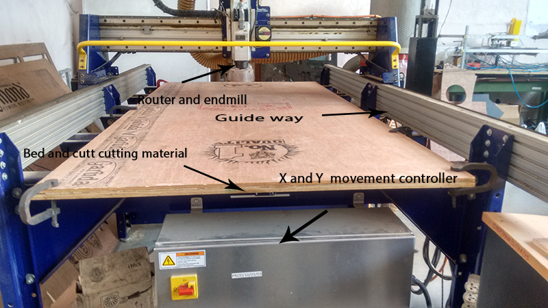 Shopbot machine at College of Engineering Pune
Tooling
We are using end-mill as a milling tool for this machine, endmill is designed to
traverse a path while cutting the material, this is the basic difference between an endmill and a drill bit.
The endmills can be a lot of type,
Center cutting or non center cutting- A center cutting endmill will help plunge the endmill as it traverses, whereas a non centered mill will not be that efficient in doing the same
Up cut/down cut- An upcut endmill is the one in which the flutes move upwards as the mill rotates thus it removes the material from the bottom and takes it to the top thus it gives you a better bottom finish, the downcut mill is the vice versa it gives better top finish
Thus a good practice would be to have a shallow cut with a down-cut endmill just enough so that we get a good top finish and the rest of the milling can be done with the up-cut endmill for better bottom finish.
Speeds and Feeds
Chipload- It is (Feed Rate/(RPM*Number of flutes))- so basically it is the amount of how quickly the material is fed to the endmill and quickly it removes the material. There is a tradeoff though, if you feed the material too fast the machine is going to scream in pain and cause a lot of heating and blackened surface finish or else if you feed the material too slow the mill is just going to rub the material and scrap it. We do not want this we want to penetrate the material but it should not be very fast too, there is always a sweet spot for every material.
The sound of the machine tells you a lot, it should sound happy as it mills, one can listen to the sound the machine makes and know wether the speed and feed rate is fine or not, this comes with spending some time with machine and making a few trials
I will not claim that I can do this with ShopBot but I can certainly tell when the Roland Modella machine is doing fine when it is milling the PCBs
Cutdepth- It basically is the amount of mill that plunges into the material for every pass it makes, too much and we might damage the end-mill and too little will be just a waste of time, as Rule of thumb it should be equal to the diameter of the mill
Stepover- This is the amount of over-lap the endmill makes when it is traversing sideways. Suppose if we have stepover equal to the diameter of the mill there will be a kind of uphill kind of protruding shap of material form in between, we dont want this. As a rule of thumb there shoul always be some overlap and it should be half the diameter of the endmill.
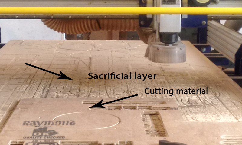
sacrificial layer and squaring
Any shop bot machine has flat layer of plywood under the main cutting material, This is where we clamp our main part to.
This layer is important or the protection of the endmill, in case the endmills plunges more than the thickness of the material it will cut into the sacrificial layer rather than the metal bed of the machine.
Flat and ball endmills- When you are doing 2.5d milling on a matrial the flat end mill is going to leave some steps as it traverses in the z direction whereas a ball end mill will give you an undulating pattern, thus one can say that a ball end mill will give us a near smooth finish
Machine software
For our shopBot machine we used Partworks as a editting software and Shopbot editor as a machine software.
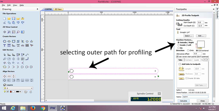
In partworks we import the file and give them the tool path and specify the cutting tool and other parameters. We have the options to rotate, mirror, copy images in this software.
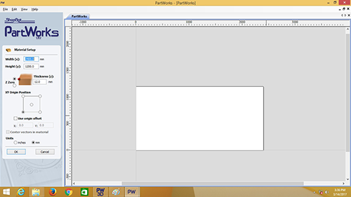
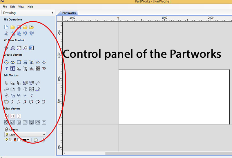
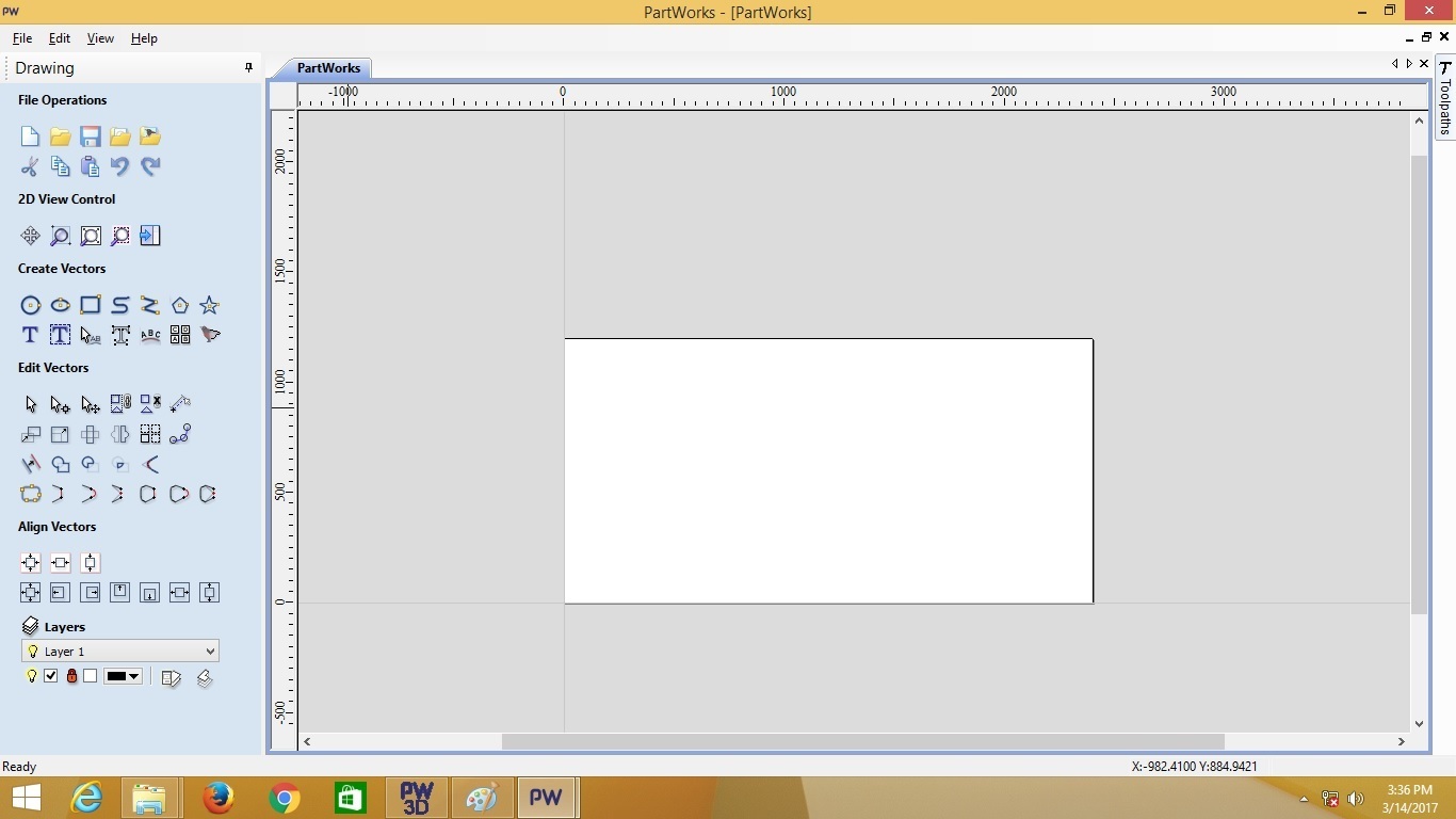 User-interface of PartWorks
The tools contol panel of the software is very easy to use and self explanatory
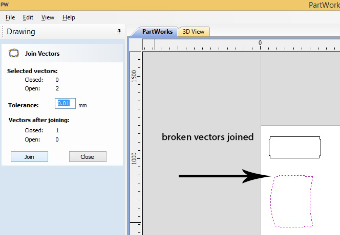
One important function this software has is the Join vectors. What usually happens is that when you import a file some lines get dislocated or erased while moving them, this functions joins those parts, this is really handy as the machine will not accept open vectors
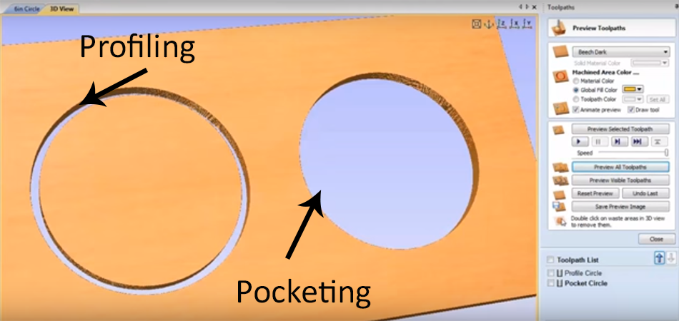
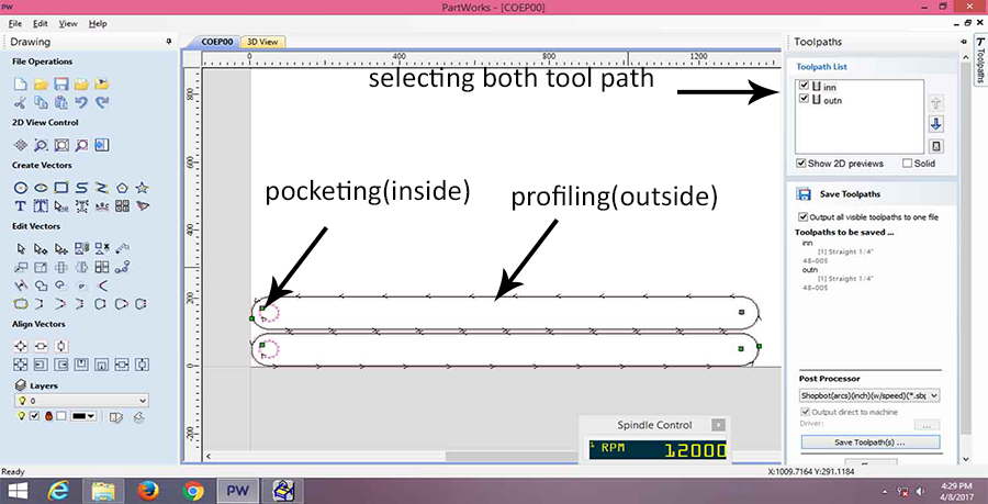
There a majorly two tool paths one is the profiling where the endmill cuts away the outside of the path it traverses, and the pocketing where the endmill cut way the inside part of the path it traverses.
My design had all the profiling tool path, as I did not make any kind of joint or lip and groove arrangement I did not have any pocketing to be done.
The difference between profilling and pocketing is shown in the figure- Courtesy Youtube
Courtesy Nishta Kaushik for the screenshots
Troubleshooting
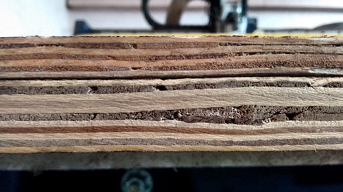
The biggest touble anyone would face while using the machine is that of the material, the plywoood is never flat and thus it lifts up a little bit when you clamp it
 Bent in the sheet
Thus we screwed the material to the bed. This helps to keep the material flat.
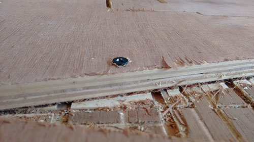
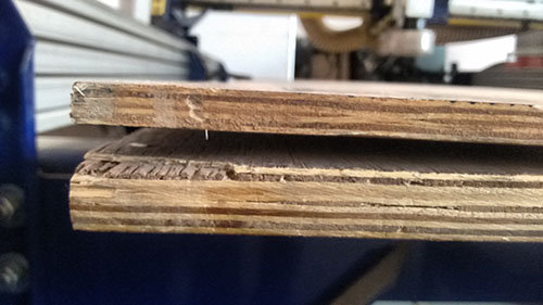
Sometimes the endmill does not reach the bottom of the material and thus the cut part has to be removed by pulling it out, this results in broken pieces or pieces with not a good finish
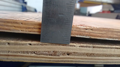
For this we have to specify the cut depth of the material a little higher than the thickness of the material, in my case the thickness of the material was 12mm I specified the cutting depth to be 12.5mm.
One important trick I learnt from the instructor is to deduct the space taken by the clamps we put on the edges to hold the material on the bed, thus while specifying the initial size of the material, we should specify 30mm less than the original.
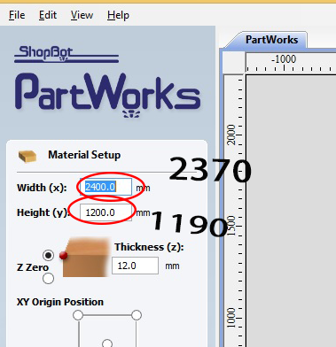 Specify the size of the material 30mm less than the original.
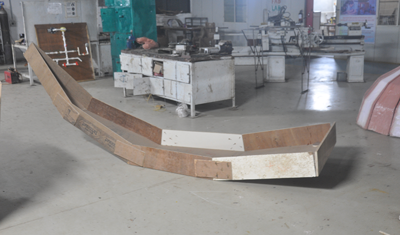
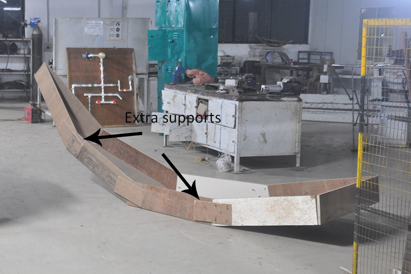
After cutting the whole object in the shopbot machine my mould is finally taking shape.
I have purposely not made the mould press fit as it will be assembled and dismantled frequently after casting and setting of the matrics, the pressfitt joints will loose the material due to friction taking occuring during the frequent dismantling and assembling
I added a few extra supports at the joints just enough to secure them, I used screws to join them
I refered Yogesh Tamhane's in his 2016 year batch assignment, he has given amazing explanation of zeroing the machine, i would like to include the same here.
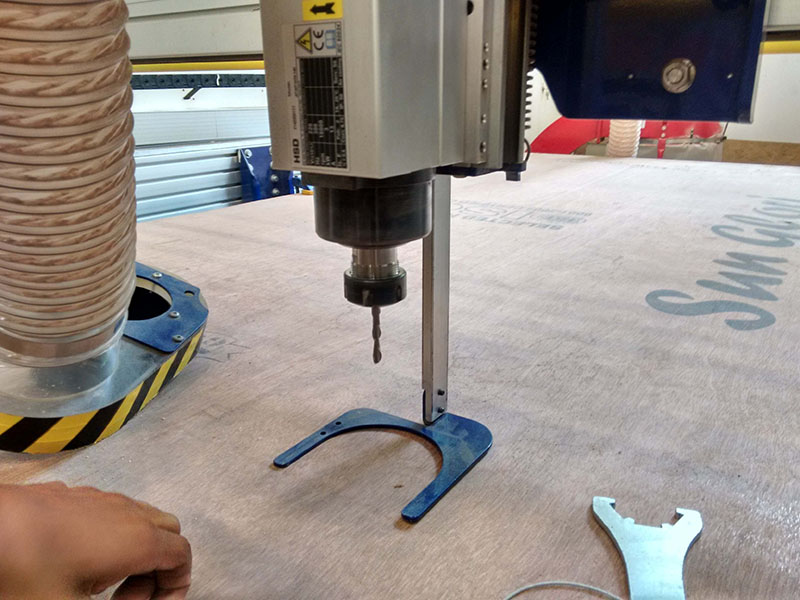
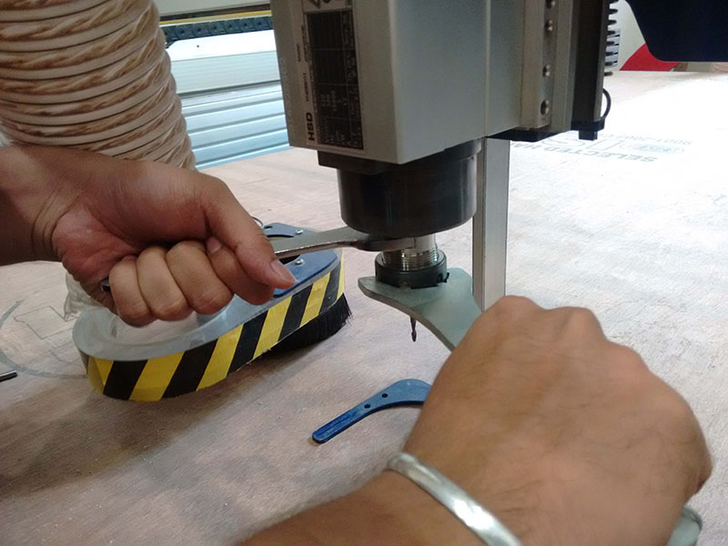
How to change tool?
Remove dust collector hose
Access the tool rack and get the appropriate tool
Get the tool changing spanner
Loose the tool holder by rotating both the spanners in inward direction and remove the tool
Load the appropriate tool, use spanners to tight but this time move them outward to tight it
Adjusting Z zero
Zeroing Z is very important activity that one should do. Doing this make the machine aware that what's the position of the tool with respect to material thickness and how much depth it has to reach for cutting/engraving. When you give command for zeroing the Z, software asks to keep the metal plate which is located at the spindle right below the tool, after this software makes the tool to go and touch the plate below and goes up 1 inch and stays there.
Basically the plate we kept below the tool is connected to the shopbot using the wire which somehow manages to identify the touch of tool and provides feedback to the software.
My experience using the machine
I loved this machine, its really fast and precise, as Neil said after this assignment you will never buy furniture from the market rather you would design it for yourself
Safety is very important,there is lot of dust generated during the process, one has to take care of it.
The endmills cost a lot almost 7000/- Indian rupee for a single bit. You really have to see where the sheet is bending and if it is bending we have to clapm it nicely to the bed.
The clamps needs to be away from the cutting part or if screws are used (as in my case)they shuld never touch the endmill while it is traversing
The mold was made when I had not decided on the composite for my dome panels, when I designed the mold I was even considering making panels made out of cement. If that was the case the cement mixture would have put a lot of load on the side walls of the mold thus I made sure that the side walls are safe by screwing them and not using a pressfit joint.
Now that I know the composite which is polyester resin and glass fiber I would have liked to use kerfing to bend the side walls, that would have saved me the fabrication time for the mould and as the kerfing is a flexible it would have helped me in demoulding
One of few realisation you get when you complete the assignment.... Thats classic FabAcademy